
This post covers the implementation of a 2-dimensional quadcopter using the Unity game engine and PID controllers for flight control. This was a recent implementation and the details are documented here in hopes that others find some of this helpful.
Expected Outcomes
Follow the walkthrough in this tutorial should hopefully provide the following:
- A Unity environment simulating 2-dimensional quadcopter flight ready for experimentation.
- A basic understanding of how PID controllers can be used in Unity (and elsewhere) as control systems.
- Basics on rotorcraft 2-dimensional dynamics.
All the covered code as well as the working project can be found in this GitHub repository. If you don’t care about the walkthrough of how and why you can grab the code and skip right to The Simulation section.
Before getting started
A few decisions were made for this simulation.
Why Unity? Unity comes with a sophisticated physics engine and makes rapid development and experimentation quick and easy.
Why Only 2 Dimensions? The problem of rotorcraft control is complex and removing a dimension allows for significant simplification. Once control in 2 dimensions is mastered, 3 dimensions can be tackled.
Why the PID Controller? Experienced Unity developers might wonder why use PID control over classic pathing techniques. The goal is to use a controller that translates to the real world. PID controllers are the go-to control loops for self-regulating systems.
Basics of a Quadcopter in 2D
By starting with simulation in 2 dimensions instead of 3, the complexity is significantly reduced.
IMPORTANT: In this article, the vertical axis is referred to as y and the horizontal axis as x. This is done to keep consistency with the x-y 2D axis in Unity. In standard notation, the horizontal axis would be referred to as y and the vertical axis as z (or x => y and y => z).
Active Forces
The drone has 3 total forces acting on it at any given time:
- A variable upward force for each propeller perpendicular to the frame and upwards
- A constant force of gravity directly downwards regardless of the frame’s orientation.
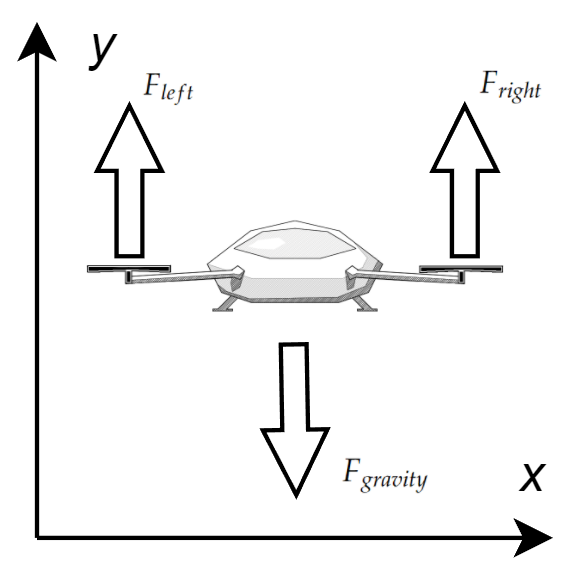
As long as the quadcopter is defined as a rigid body with mass, Unity takes care of the gravitational force. The force (or thrust) of the rotors is what the control system has to manage.
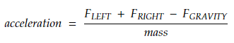
Control
Acceleration of the simulated quadcopter can be controlled by changing the thrust of the rotors.
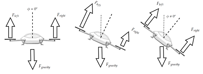
When the quadcopter is level with the ground, acceleration is only applied along the y axis. Increasing the thrust of the rotors in this orientation causes the quadcopter to accelerate up and decreasing thrust causes it to accelerate down.
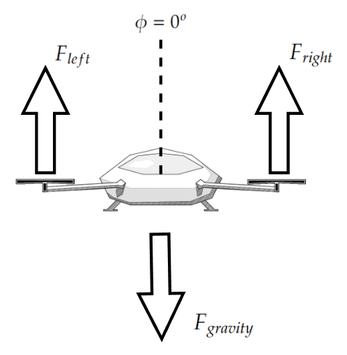
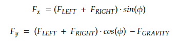
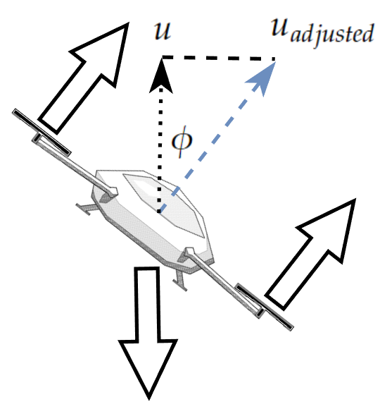
When the quadcopter is tilted at an angle (we will call this angle phi or 𝜙) relative to the ground the force from the propellers begins to apply both horizontal and vertical acceleration. Maintaining thrust in this orientation increases horizontal velocity (y-axis).
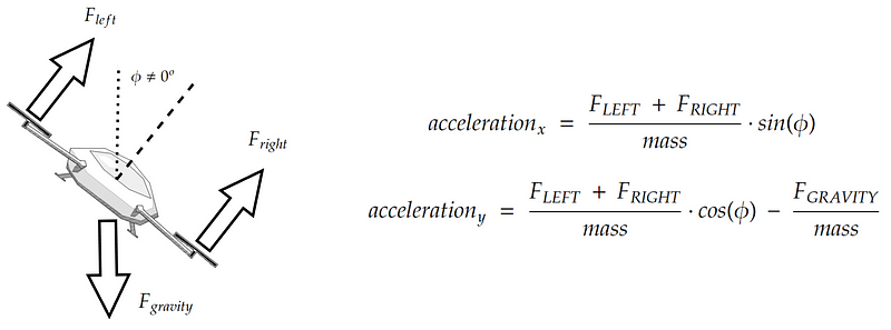
or …
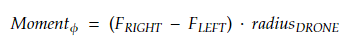
Lastly, in order to change the angular orientation of the quadcopter (or roll), the thrust between the rotors needs to vary in order to produce torque (or moment). This moment is proportional to the difference between the forces and the distance between the rotors.
NOTE: Quadcopters in 3 dimensions also need to control yaw, which is torque (or moment) arising from the motors spinning. Luckily with only 2D there is no third dimension for the drone to yaw around.
The dynamics above allow for a fairly simple control system where only the overall thrust for the quadcopter’s linear acceleration and the difference in forces between the rotors for rotation need to be determined. This is typically expressed in terms of u1 and u2, where u1 dictates total thrust and u2 the total moment.
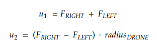
These are the values that the PID controller needs to determine.
The Control System
The PID controller is a control loop approach that continuously supplies a system with an input (like thrust, voltage, resistance, etc.) and adjusts this input based on how well the system performs over time.
The general idea revolves around providing the PID controller with 3 coefficients — Position, Integral, and Derivative. These coefficients are used by the algorithm to determine how to scale the output control value as the system gets closer or further away from its goal. We won’t get into the details behind exactly how PID controllers work but getting more knowledge on the subject is highly recommended. I have found the series here to be an excellent introduction.
The system uses 2 PID controllers to solve the 2D quadcopter control problem;
Altitude controller — Provides the drone with a thrust value required to drive the quadcopter to a desired high.
Attitude controller — Provides the drone with moment values to help stabilize the aircraft.
Here is what the control loop looks like. Note that only the desired elevation (y-axis) is provided as an overall system input. The controller’s job is to drive the quadcopter to that altitude while ensuring a balanced orientation.
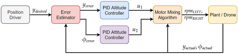
Position Driver — Represents the general control loop input — altitude.
Error Estimator — Component responsible for providing the PID controllers with the deviation between the desired state (altitude and neutral orientation) and actual values.
PID Altitude Controller — This PID controller uses the position error from the error estimator to derive a u1 value or the overall desired vertical thrust.
PID Attitude Controller — This PID controller uses the orientation error from the error estimator to derive a u2 value or the required torque.
Motor Mixing Algorithm (MMA) — This algorithm uses u1, u2 and combines them with the drone’s current orientation to determine the required total thrust for each rotor.
Plant / Drone — The physical (or virtual) drone that interacts with the environment and provides feedback to the system with actual state values.
The Code
With all of that out of the way let’s get to building the actual simulation. Unity is used due to its built-in physics engine. The GitHub repository can be found here containing a working instance of the simulation.
One might be able to get away without any Unity experience but getting at least some familiarity is highly recommended even if you don’t have any game development aspirations. Brackeys has some fantastic resources such as this one that can get you started.
The folder structure
The project was organized into the following file structure.
├───Prefabs
│   ├───Quadcopter - prefab of the complete quadcopter
│   └───Thruster - prefab for a thruster object
├───Scenes
│   └───Main - the only scene in the project
├───Scripts
│   ├───PIDController - PID script obejcts
│   ├───Quadcopter - script for the quadcopter object
│   ├───FlightController - script to bring everything together
│   └───Thruster - script containing control for rotor objects
The scene
All scene and camera default values are kept and the scene is only updated with the following objects:
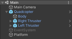
Quadcopter — The quadcopter, contains a flight controller, a rigid body frame, and two thrusters.
Platform — A static rigid body providing the quadcopter with a stable liftoff surface.
Event System — Default event system object which was disabled as it is not used.
Main Camera — Default camera object.
The code
The repository with all the code can be found here. The script objects are described at a high level with a few notable lines of code called out.
Thruster.cs
This script is associated with each rotor and provides the quadcopter with thrust. At every physics engine tick, the rotor script computes the force it should be producing using a thrust coefficient and the simulated blade speed.
Rotor thrust can be updated by calling the setRevolutionTarget() function and passing the desired RPM value. The thruster then updates the RPM value continuously until the target is reached using the updateRevolutionRate() function.
Quadcopter.cs
This script represents the quadcopter object, it is mapped to the attached rotor objects and contains the Motor Mixer Algorithm code.
The u1 value is adjusted to account for gravity by multiplying by Cos(phi), where phi is the drone’s current angular orientation angle. The u2 value (moment input) is applied as a positive to the left rotor and a negative to the right to generate the required moment.
Note that the values as passed directly as units of force to the rotors. This can be done because of the general flexibility of PID control systems. The control loop scales the magnitude of the inputs based on how the system reacts.
PIDController.cs
This is the main PID control script and the core logic is packed into the GetPIDOutput() function. This method is called every time a new value needs to be estimated. p, i, and d are the gain magnitudes, and kP, kI and kD are the coefficients that can be tweaked through the FlightController.cs script to change the PID controller’s performance.
Here is a great resource to learn move about PID control logic.
The integral term is updated using the model’s previous integral value and is intended to provide the model with a type of “memory”. This is great at helping the system adapt to unknown variables but it can also get us into trouble. For example, if the drone is still some significant distance from the target destination but has reached its maximum velocity the integral term will continue to grow past the maximum. This will cause sub-optimal deacceleration as the system will have to undo the winded-up excess. A more detailed explanation can be found here and it discusses the concept of preventing this over-saturation by the clamping (or stopping accumulation) of the integral term if the PID output exceeds the system capability threshold.
FlightController.cs
This is the script that pulls everything together. The desired position and Thrust, and Roll PID coefficient can be set through this object.
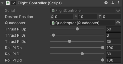
At every physics engine update, this script computes the current error state, passes the error to the PID controllers, and feeds the resulting u1 and u2 values through to the drone Motor Mixer Algorithm.
The Simulation
The code in the repo should run as-is out of the box but how the parameters of the simulation can be manipulated are covered below.
Thrusters
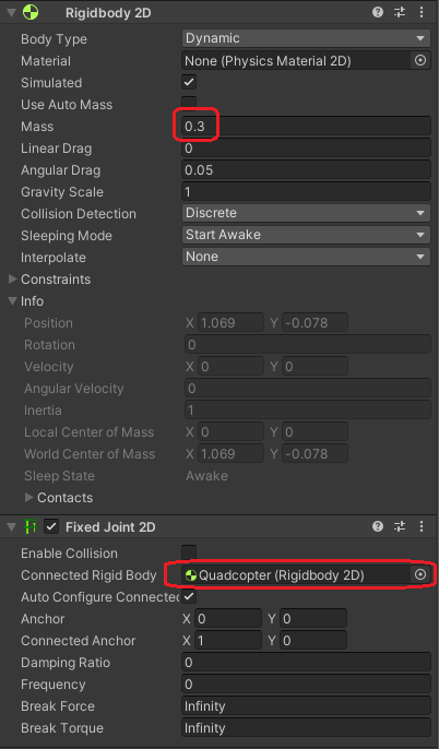
The drone has left and right thrusters, these can be manipulated separately, however for best results their parameters should be identical. Each thruster also has a rigid body with a defined mass (0.3) and this rigid body is attached to the parent drone body using a 2D Fixed Joint.
The main Thruster.cs parameters to configure would be the thrust coefficient, maximum RPM, and the spinup rate.
Quadcopter
The quadcopter also has a rigid body with a defined mass (1) along with a simple collider to prevent it from passing through the surface platform.
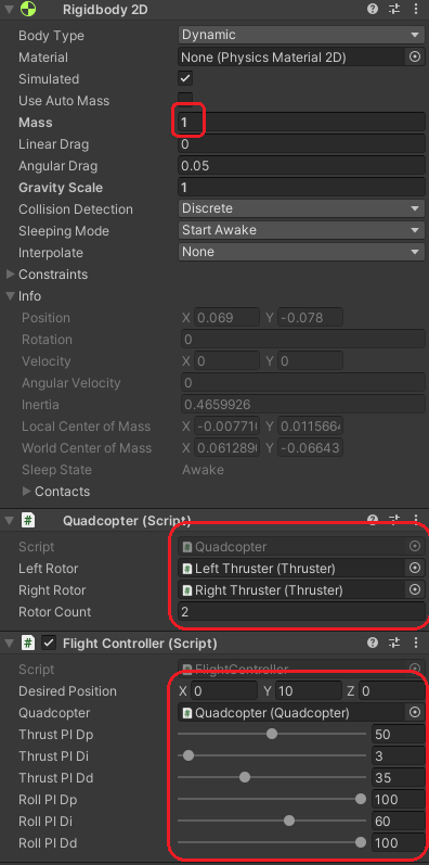
The rotors and rotor count are set in the Quadcopter.cs script and the target position and PID control coefficients in the FlightControl.cs script.
Running the Code
When the scene is run, the quadcopter lifts off the ground, moves towards the specified altitude, and settles there.
*The red lines are debug lines showing thrust.
The P thrust values can be modified to change how quickly the drone reaches the desired high.

The D thrust value dictates how smooth our trajectory is and can be used to minimize overshooting at a cost of slower convergence.

The I thrust value allows the system to overcome unforeseen disturbances in the environment and have a smoother recovery. The drone uses the integral term value of 2.5 which allows it to account for the force of gravity that was omitted from the model altogether. Here is what it looks like with the integral term set to 0 — the drone fails to reach the target altitude of 10.

The roll PID coefficients provide the same role but for pitch. Here is what it looks like when the orientation and position of the drone are disturbed.
Conclusion
If you got this far you should either have a working 2D quadcopter Unity simulation or at least the knowledge of how to create one. In future articles, I hope to increase the complexity of this simulation, including automated motion planning and the adaptation to 3 dimensions.
Please let me know if I have made any errors or omitted anything. Feel free to post any questions as comments as well.
Happy coding!